Generate and print | Evidence and continuation | Family instructions | Standard stud | Printing outcomes
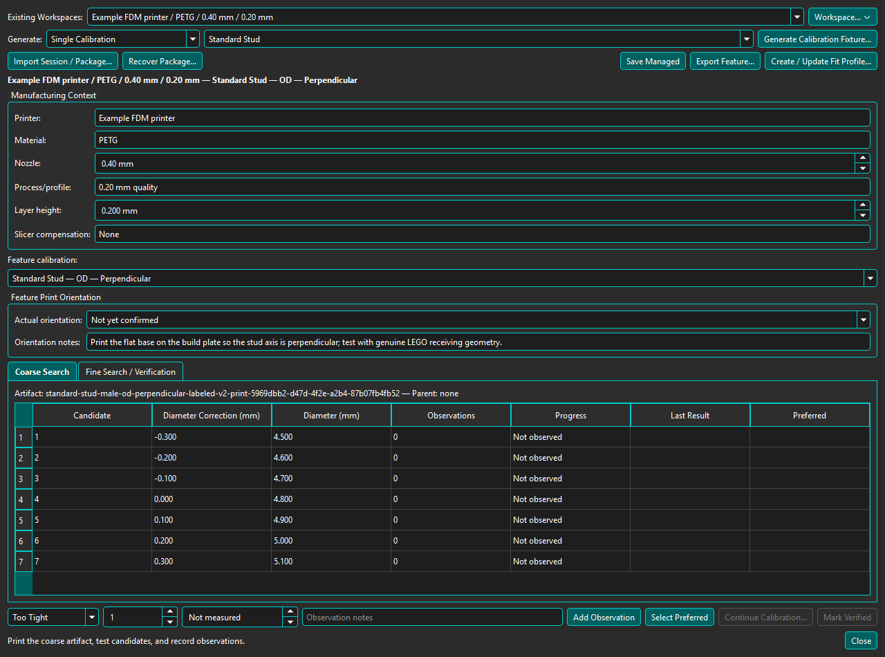
Use Tools → LEGO Fit Calibration... to work in a manufacturing-context workspace. The last-used workspace opens automatically; choosing another Existing Workspaces entry immediately loads it. If pending edits have not been autosaved, choose Save to switch or Cancel to keep editing the current workspace. A failed save also keeps the current workspace active. Printer, material, nozzle, process, layer height, and common slicer-compensation notes are entered once and shared by its feature calibrations. Choose Single Calibration, select a family, and click Generate Calibration Fixture...; each feature retains its own actual print orientation, artifact lineage, observations, and verification state.
New Workspace... creates an empty managed manufacturing context that remains available after restart. The new workspace becomes current immediately; choose Single, Recommended, or Custom generation without restarting. Actual feature orientation and orientation notes become available after a feature calibration exists. Delete Selected Workspace... removes only the selected workspace's managed sessions and associated Fit Profile after confirmation; BrickSuite first writes a recoverable backup and displays its location. External calibration packages are not changed. Deleting the active workspace selects a remaining workspace automatically; deleting the final one clears the active context and saved preference. If a previously used workspace is unavailable, BrickSuite selects the first valid workspace without creating one.
Intended orientation describes the generated fixture, such as Perpendicular. A feature label uses recorded actual orientation when present; otherwise it uses the modeled fixture orientation. Actual orientation: Not yet confirmed still requires you to record how you physically printed the fixture. Importing a package and displaying its intended orientation do not create physical evidence. Older records lacking either orientation show Legacy orientation unspecified; their history is not rewritten.
LEGO Fit feature names consistently identify the family, measured feature or variant, and feature-axis orientation relative to the build plate—for example, Standard Stud — OD — Perpendicular and Stud Receiving Clutch — Tube Wall Cell — Perpendicular. A newly generated fixture uses that full name when it fits safely, otherwise its fixed catalog abbreviation (such as STUD-OD-PERP). Historical artifact identities and calibration evidence are not renamed.
Choose Single Calibration for one family, Recommended Calibration Package for the four-family core, or Custom Calibration Package to choose supported members. Review the package plan before generation. See package contents, import, recovery and Fit Profiles.
Standalone Stud OD fixtures and combined calibration zones have recessed underside feature labels. Where the full Feature calibration name cannot fit safely, an abbreviated label is used and recorded beside the full name in the package manifest for unified zones. These labels are separate from the Candidate #1 markers and do not replace them.
Source-dependent families use the installed library configured in Edit → Settings → 3D Models. Missing source Parts or dependencies prevent generation; BrickSuite does not substitute generic geometry or require repository-local files. Generators, definitions, labels, and this Help ship with the application. Printable packages belong in Documents; managed sessions, workspace records, Fit Profiles, and history belong in application data, with the last-workspace preference in application settings.
Test insertion and removal without forcing the pin. Record each candidate as too tight, acceptable, preferred, too loose, or unable to evaluate. Repeat the preferred candidate and its neighbors before selecting a candidate. A single trial is experimental evidence, not a verified calibration.
Keep the printer, material, nozzle, layer settings, orientation, and slicer dimensional settings consistent. Hole/XY compensation, elephant-foot compensation, shrinkage compensation, or scaling can change the result. Candidate values are a search range, not official LEGO tolerances. Only applicable, explicitly Verified evidence can contribute to a production Fit Profile.
Select Preferred records the best candidate observed so far; it is not verification. Mark Verified explicitly confirms sufficient repeat and neighboring-candidate evidence. Use Save Managed to save locally or Export Feature... for portable session evidence. After verification choose Create / Update Fit Profile... to contribute compatible evidence to printing corrections.
The Coarse Search and Fine Search / Verification tabs show separate stages of the selected feature. Coarse Search can review earlier range-extension artifacts from the managed lineage; those historical rows are read-only, while Fine Search / Verification retains the later evidence and Verified result. New continuation sessions carry immutable snapshots of earlier observed stages, and Export Feature includes that available lineage for portable import. If an older session references a parent whose evidence was never saved, the missing history is reported as unavailable rather than reconstructed. Generating a fine search writes its versioned 3MF at 100% scale and opens its empty candidate rows in the Fine tab. Verification requires repeated consistent evidence and observed candidates on both sides. Verified feature corrections from the same manufacturing context can accumulate in one Fit Profile while retaining their feature-specific orientation and source-evidence identity. Import Session / Package... and Export Feature... preserve portable per-feature JSON compatibility.
Continue Calibration supports source-faithful fine/repeat stages and boundary extension within each generator's established range, including frictionless Technic Pin continuation. If a requested extension exceeds a bounded source contract, BrickSuite explains why it is unavailable. It never substitutes generic geometry or marks a boundary winner Verified. Record actual physical orientation and observations independently of the fixture's intended orientation.
If every candidate produces the same directional result, record each result without selecting a Preferred candidate. When all candidates are Too Loose or all are Too Tight, Continue Calibration... automatically offers a coarse-range extension in the dimensionally correct direction. The parent observations remain unchanged and the extended child artifact starts with fresh evidence.
If the preferred candidate is at either end of a search ladder, the optimum is not bracketed. BrickSuite identifies the lower or upper boundary and offers an overlapping extension in that direction before verification. Height observations remain provisional until they are repeated using the ultimately selected stud diameter context.
When a preferred candidate is inside the tested range, Continue Calibration... offers either an optional finer search or a direct three-candidate verification print containing the selected correction and its immediate neighbors. Direct verification still requires fresh physical observations, consistent repeats, evidence on both sides, and explicit Mark Verified; it does not turn the earlier search result into Verified evidence.
Continuation sessions inherit the parent printer, material, nozzle, process, layer height, printed orientation, orientation notes, and slicer-compensation context. Session labels identify the functional feature, calibrated dimension, stage, and available manufacturing context. The candidate table reports preferred-repeat and neighbor-evidence progress; hover over a disabled Mark Verified button to see the remaining prerequisite.
The Technic Hole calibration strip tests printed female passages with a genuine LEGO Technic friction pin. Print its broad flat face on the build plate at exactly 100% Scale. The chamfered end identifies candidate 1; candidates run left to right.
Friction Technic Pin calibration uses a separate seven-candidate fixture derived from official confric5 geometry. Candidate #1 is beside the raised side marker. The fixture varies only the friction-ridge envelope from 4.85 mm through 5.15 mm while retaining the 4.80 mm core, bore, compliance gap, entry transitions, and engagement length. Print at 100% with pin axes perpendicular to the build plate and compare candidates in two genuine LEGO Technic receiving Parts. An applicable Verified perpendicular Friction Technic Pin correction can adjust the recognized friction-ridge envelope in ManufacturingMesh and Auto Fit while preserving the protected core, bore, gap, and engagement geometry. Unsupported or unverified features remain nominal.
The family selector also supports Ball Socket, Pin / Barrel Hinge, Interleaved-Finger Hinge, Click Hinge, Retained Rotating Wheel, and Plain Round-Bore Wheel using their installed LDraw sources. Choices are limited to supported fixture orientations. Unavailable sources and prerequisites are explained in the selector; Stud Height requires matching Verified Stud OD evidence. New continuation fixtures use three, five, or seven candidates, with fresh observations and preserved earlier Coarse evidence. Each separate source-backed candidate retains its printed numeral or dot-count identification. Consult the new companion for its correction: a continuation's center candidate is not necessarily nominal.
Choose Single Calibration → Technic Hole and Generate Calibration Fixture... to create a coarse calibration for a female Round Technic passage printed with its axis parallel to the build plate. Print the artifact on its broad flat base at 100% scale and test candidates 1–7 left to right with a genuine LEGO Technic pin. The candidates span 4.80–5.40 mm in 0.10 mm steps. Parallel evidence remains separate from perpendicular evidence and cannot affect production Fit until its own repeat, neighbor, and explicit verification requirements are complete.
Technic Axle calibration varies the ordinary male cross profile's tip-to-tip envelope while preserving the cross-arm width and engagement length. Early Technic Axle Hole fixtures varied tip-to-tip clearance and remain preserved as historical physical evidence; they are never production-applied. Microscope inspection identified the female arm-opening width as the controlling interference, so the corrected v2 fixture holds tip-to-tip at 5.10 mm and varies arm width. A compatible Verified profile can independently apply the perpendicular male tip-envelope correction and female v2 arm-width correction to ManufacturingMesh and Auto Fit. Unmatched orientations remain nominal. Reduced, semi-reduced, rounded, sliding, D-axle, and other specialized variants remain separate families.
Stud Receiving Clutch calibration offers distinct TubeWallCell and PostWallCell variants. PostWallCell represents ordinary one-wide receiving geometry built around an official stud3 post and its surrounding walls. Its seven-candidate artifact varies only the 3.20 mm nominal post outside diameter from 2.90 mm through 3.50 mm, while wall position, stud pitch, seating depth, and post height remain fixed. Candidate #1 is beside the wall notch; test both bays with genuine LEGO studs. Applicable Verified Tube Wall Cell and Post Wall Cell corrections can adjust their recognized outside diameters in ManufacturingMesh and Auto Fit for the matching printed orientation. Tube correction preserves the inner bore; post correction preserves the surrounding walls, post height, seating depth, and stud pitch. Missing ownership or compatible Verified evidence leaves the feature nominal.
WallPocket is a separate square, wall-supported stud receiver, not a tube or post. For source parts with a certified LDraw pocket and matching outer shell, BrickSuite retains its 4.80 mm nominal opening in Prepared Mesh. ManufacturingMesh can adjust only the four inner pocket walls when a matching, physically Verified opening-width correction exists for the Print Orientation; pocket floor and exterior remain unchanged. Circular anti-stud bores are not WallPocket geometry.
To calibrate WallPocket, select Stud Receiving Clutch under Single Calibration, then choose Wall pocket. Its compact shallow strip has seven independent square openings, 4.50–5.10 mm in 0.10 mm steps; Candidate #4 is nominal 4.80 mm. Print the flat base down with pockets open upward at 100% scale, record the actual process and slicer compensation, and test candidates with genuine LEGO studs. The Verified opening correction applies to both brick-depth and plate-depth WallPocket production contracts; their source geometry and pocket depths remain distinct. Existing depth-specific managed sessions and profiles remain valid. Continue Calibration can create an evidence-linked verification or fine-search fixture; Mark Verified is available only after the normal physical evidence requirements are met.
AntiStudBore is a centered stud-into-bore connection identified by certified stud4o source geometry, not by any generic round hole or ordinary underside tube. The nominal inner diameter is 4.80 mm. The separate seven-candidate perpendicular fixture varies only the centered bore diameter from 4.50–5.10 mm; print its flat base down with bores open upward and test with genuine studs entering the center. Candidate #1 is beside the wall notch. No correction is applied to ManufacturingMesh until physical observations are explicitly Verified in the matching workspace; unsupported orientations remain nominal.
Standard Bar recognizes certified, capped, standalone LDraw bar cylinders such as Parts 30374 and 87994. Their nominal diameter is 3.20 mm; other rods, antennas, pins, axles, studs, and receivers are not inferred from diameter alone. Select Standard Bar under Single Calibration for a perpendicular seven-bar fixture (3.05–3.35 mm in 0.05 mm steps, Candidate #4 nominal). Print its flat base down at 100% scale, with bars vertical and Candidate #1 beside the notch. Test candidates in the same genuine standard-bar grip or clip, record the actual process and repeat/neighbor observations, and explicitly Verify the result. A compatible Verified perpendicular profile enables Standard Bar ManufacturingMesh and Auto Fit; only the certified cylindrical surface is adjusted. Without applicable Verified evidence, Source and Prepared geometry remain nominal.
C-Clip / Bar Receiver calibration recognizes the certified rounded clip6.dat receiver used by parts such as 11476 and 11399. Its nominal 3.20 mm internal contact arc has an open, compliant throat; it is not a simple round hole. Choose perpendicular or parallel when creating the seven-clip fixture. Each separately identified fixture couples contact-arc size and throat opening from 3.05 to 3.35 mm in 0.05 mm steps, with Candidate #4 nominal. Print the flat base down at 100% scale with the clip axes vertical for perpendicular or horizontal for parallel; Candidate #1 is beside the notch. Snap the same genuine 3.20 mm LEGO bar sideways into each candidate and record seating, retention, play, removal, stress and repeatability. A generated or imported session is not Verified until physical observations satisfy the normal evidence rules. Compatible Verified perpendicular or parallel evidence enables C-Clip ManufacturingMesh and Auto Fit only for its matching print orientation; evidence from one orientation never substitutes for the other. Only the certified inner contact arc and adjacent throat are adjusted, while outer arms and unrelated geometry remain nominal. Unsupported orientations and missing evidence retain the nominal Prepared Mesh. Part 11399 still has a separate preparation limitation.
Ball Joint recognizes a certified male joint8ball.dat with its owned spherical 8-8sphe.dat head, nominally 6.40 mm diameter. It does not infer a Ball Joint from an arbitrary sphere, decorative knob, or socket. Select Ball Joint under Single Calibration and choose perpendicular or parallel orientation. The perpendicular seven-ball fixture spans 6.10–6.70 mm in 0.10 mm steps, with Candidate #4 nominal; the separate parallel fixture spans 5.80–6.70 mm in 0.15 mm steps, with Candidate #5 nominal. Print flat-base down at 100% scale, with stems in the selected orientation and Candidate #1 beside the notch. For the parallel fixture, keep slicer supports off the spherical fit surfaces. Test each ball in the same genuine LEGO joint8 socket and record snap-in, articulation, retention, removal, stress and repeatability. An applicable Verified Fit Profile enables ManufacturingMesh and Auto Fit only for its matching print orientation; parallel and perpendicular evidence never substitute for each other. A profile may still be selectable for other independently compatible features while the Ball Joint remains nominal. Correction affects the certified spherical fit surface, tapering to the unchanged stem junction; Source and nominal PreparedMesh are not modified. Without compatible Verified evidence or with unsupported orientation, the Ball Joint remains nominal.
Ball Socket (friction type) uses a source-faithful calibration fixture and managed companion session. Its seven candidates couple spherical contact and retaining-mouth clearance from −0.30 to +0.30 mm in 0.10 mm steps; Candidate #4 is the nominal 6.40 mm contact reference. Print the seven tiles on their smooth long sides at 100% scale, with the socket mouths horizontal and above the bed. Each tile has an embossed exterior number matching its session candidate row. Keep supports off the contact and throat. Test every candidate with the same genuine LEGO 6.40 mm joint8 ball, recording insertion, seated play, articulation, retention, removal, stress and repeatability. An applicable Verified parallel-orientation Fit Profile enables Auto Fit and ManufacturingMesh to adjust the certified socket contact and retaining mouth together; a Verified zero correction preserves nominal geometry. Without applicable Verified evidence, the socket remains nominal. The free-moving joint8socket2.dat variant is a different mechanism and is not covered by this calibration.
Pin / Barrel Hinge (first contract) identifies the two hollow pins on the 3938 top and the two open retaining barrels on the 3937 base from their certified LDraw surfaces. It does not include interleaved-finger, click, Technic-pin, or generic cylinder hinges. The seven-piece parallel fixture varies both male pin outside diameters from 3.05 to 3.35 mm in 0.05 mm steps; four-dot Candidate #4 is the nominal 3.20 mm pair. The pin bores and shoulders remain unchanged. Print each dot-marked top on its long exterior plate side at 100% scale with both pin axes horizontal and elevated from the bed. Keep supports off the pins and bores. Repeatedly assemble each candidate with the same genuine LEGO 3937 base and record assembly force, rotational freedom, retained alignment, binding, play, removal, wear, and repeatability. Import the companion managed session to record results. ManufacturingMesh and Auto Fit use only an applicable Verified parallel male-pin correction to adjust the two certified 3938 exterior pin walls; the 1.60 mm bores and 3937 barrels remain nominal. Unsupported orientation or missing Verified evidence does not alter the hinge pins.
Interleaved-Finger Hinge recognizes the certified three-finger h2.dat and complementary two-finger h1.dat geometry on the 4275/4276 hinge halves. The first parallel fixture uses seven dot-marked 4275a three-finger pieces and varies only the two source-owned contact-bump protrusions from 0.15 to 0.45 mm in 0.05 mm steps; Candidate #4 is the unmodified nominal 0.30 mm geometry. Print the pieces on the exterior plate edge opposite the fingers, with the finger axis parallel to the bed. Keep supports off the fingers and bumps. Test each with the same genuine 4276a mate, recording assembly, repeated rotation, axial alignment, play, binding, retention and wear in the imported managed session. This is not the 3937/3938 pin-and-barrel mechanism. ManufacturingMesh can export the certified hinge at nominal geometry with an explicit nominal / unverified indication; this does not claim physical verification. Once an applicable parallel Verified Fit Profile is available, Auto Fit and explicit profile selection use its contact-bump adjustment on the two certified 4275a bumps without changing the fingers or the 4276a mate.
Click Hinge recognizes the paired clh1.dat single-finger arrestors and the indexed clh4.dat dual-finger mate in certified LDraw source geometry. Catalog Part 76385 contains the 30345.dat click insert as a nested LDraw source component; 30345 is the insert used for the calibration fixture, not the primary catalog-part acceptance case. Part 30394 is an indexed mating control. This contract does not include pin/barrel, interleaved-finger, Technic, or generic cylindrical hinges. The seven-piece parallel fixture uses source-derived 30345 click-lock inserts and varies the two arrestor contact regions together by -0.15 to +0.15 mm in 0.05 mm steps. Four-dot Candidate #4 retains the nominal 2.186 mm arrestor radial reach; the bearing and attachment remain unchanged. Print the dot-marked pieces on their long exterior sides at 100% scale, with the hinge axis parallel to the bed and supports off the contacts. Engage each with the same genuine clh4.dat mate and record assembly, indexed rotation, holding torque, release force, play and wear in the companion managed session. For a certified arrestor and applicable parallel Verified Fit Profile, ManufacturingMesh and Auto Fit use the profile's paired-arrestor adjustment while retaining the bearing, attachment, indexed mate, Source, and nominal PreparedMesh. A missing, unverified, or orientation-incompatible correction does not adjust the hinge.
Retained Rotating Wheel covers the certified wpin2a.dat/wpin.dat wheel-holding pin and wpinhol2.dat notched bearing. Catalog Parts 4488 and 30027b are the first physical reference pair; a plain round-bore wheel is a different interface. The seven small 30027b-derived wheels have one to seven raised dots on their non-fit outer faces. Print them flat at 100% scale with the bearing axes perpendicular to the plate and supports out of the bearings. The coupled bearing-and-notch opening ranges from 3.05 to 3.35 mm in 0.05 mm steps; four dots mark the nominal 3.20 mm opening. Repeatedly test each printed wheel on the same genuine 4488 wheel pin for snap force, retention, free rotation, radial play, removal, and wear. Import the companion managed session to record observations. ManufacturingMesh and Auto Fit use only an applicable Verified perpendicular bearing-and-notch correction. The wheel exterior, Source, and nominal PreparedMesh stay unchanged; unsupported orientations or missing Verified evidence remain nominal.
Plain Round-Bore Wheel is a separate contract for the certified 30027a continuous blind bearing and its 4488 wheel-holder pin reference. The nominal 3.20 mm bore has a closed axial stop, unlike the retained 30027b notched-entry bearing. Its seven source-derived coarse candidates vary the bore from 2.90 to 3.50 mm in 0.10 mm steps; four raised dots identify the nominal candidate. Print flat at 100% scale, opening upward and bearing axis perpendicular to the build plate, without supports in the bore. Repeatedly use the same genuine 4488 pin and record insertion, rotation, radial play, retention/slip, removal, and wear in the managed session. If the Preferred candidate is at a boundary, Continue Calibration generates another source-faithful, dot-numbered blind-bore fixture while preserving prior evidence. ManufacturingMesh and Auto Fit use only an applicable Verified perpendicular plain-wheel correction from the selected Fit Profile. They change the continuous bearing while preserving the closed stop, exterior, Source, and nominal PreparedMesh; the retained 30027b correction is independent. Unsupported orientations and missing or unverified evidence remain nominal.
Choose Single Calibration → Standard Stud, click Generate Calibration Fixture..., and select outside diameter or height to create a managed calibration for an ordinary solid stud printed with its axis perpendicular to the build plate. The nominal LDraw stud is 4.8 mm outside diameter and 1.6 mm high. Each coarse artifact has seven candidates, numbered left to right, from -0.30 mm through +0.30 mm in 0.10 mm steps.
Calibrate outside diameter first with genuine LEGO receiving geometry; compare insertion, retention, and removal without forcing the parts. Calibrate height separately afterward; BrickSuite requires and automatically uses the Verified diameter correction from the selected manufacturing workspace. Compare complete seating, vertical gap, bottoming, and engagement depth. When an earlier height experiment has a Preferred candidate, BrickSuite creates a focused three-candidate verification artifact around that result while keeping the Verified OD fixed. This sequence keeps radial clutch and axial seating evidence independent.
Print calibration artifacts at exactly 100% Scale using the recorded printer, material, nozzle, process, orientation, and slicer compensation. Fine search, repeat evidence, and explicit verification follow the same managed-session rules as the Technic experiment. Candidate values are search values, not official LEGO tolerances. Use Create / Update Fit Profile... after explicit verification to make supported Stud corrections available to ManufacturingMesh and Auto Fit under the orientation and OD/height compatibility rules above.